Mechanical Madness - [HTB UNICTF 2021 - Qualifiers]
The Challenge⌗
For this challenge we had the following files :
- cpu.circ (A very big XML file that describe the processor)
v2.0 raw 10000a 100101 10100 130000 100101 e0000 40000:start movl ax, 10 :sub1 movl bx, 1 sub bx cmp ax, ax movl bx, :sub1 jnz rst:start movl cx, 10 clr movl bx, 1 movl dx, 0 mmiv 0x0, dx movl bx, :sub4 call bx, 0 mmov ax, 0x0 movl bx, :sub5 call bx, 0 :sub1 movl bx, 1 movl dx, 0 push dx, 0 movl bx, :sub5 call bx, 0 movl bx, 1 sub bx, 0 cmp ax, ax movl bx, :sub1 jnz movl bx, :sub4 call bx, 0 :sub2 movl bx, 0 mmiv 0x1, bx mmiv 0x2, bx :sub3 pop ax, 0 movl bx, 1 movl dx, 0 movl bx, :sub5 call bx, 0 mmov bx, 0x1 msk mmiv 0x1, bx mmov bx, 0x2 mskb mmiv 0x2, bx movl ax, 0xff cmp bx, ax movl bx, :sub3 jl movl bx, 0 mmov dx, 0x1 movl cx, 1 movl cx, 0 movl bx, :sub2 jmp bx, 0 :sub4 movl ax, 0x05 movl bx, :sub5 call bx, 0 movl bx, 1 sub bx, 0 cmp ax, ax movl bx, :sub4+1 jnz ret :sub5 movl cx, 4 movl cx, 0 ret
Processor Analysis⌗
Once we open the cpu.circ in logisim as stated, we can see that we have a whole processor that shows up :
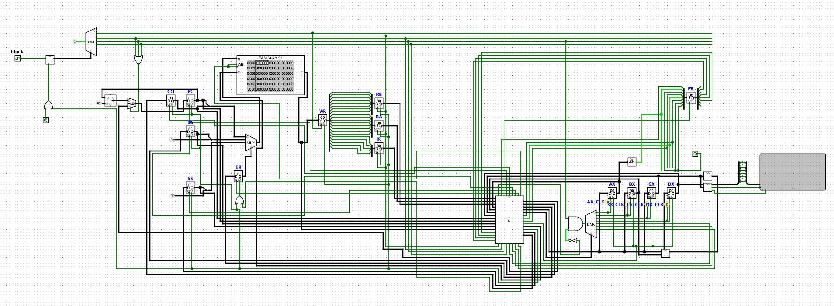
This processor is an electronic circuit powered by a clock. The first interesting part of the circuit are :
 Fig 1. Clock Cycle
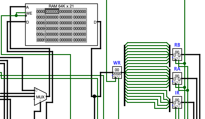 Fig 2. RAM and instruction loading
On Fig 1, we can see that the clock system is gonna cycle on 5 wires. The two first ones are the one coming from the top on Fig 2. The first wire is gonna power the WR register and the last four are respectively named Decode, Execute, Store and Clear. We can see on Fig 2 that a typical cycle will load the content of the current element (3 bytes) of the RAM in the WR register and then split its three bytes in 3 different registers : IR, RA and RB. Those bytes are then used by the CU module which probably stands for Control Unit :
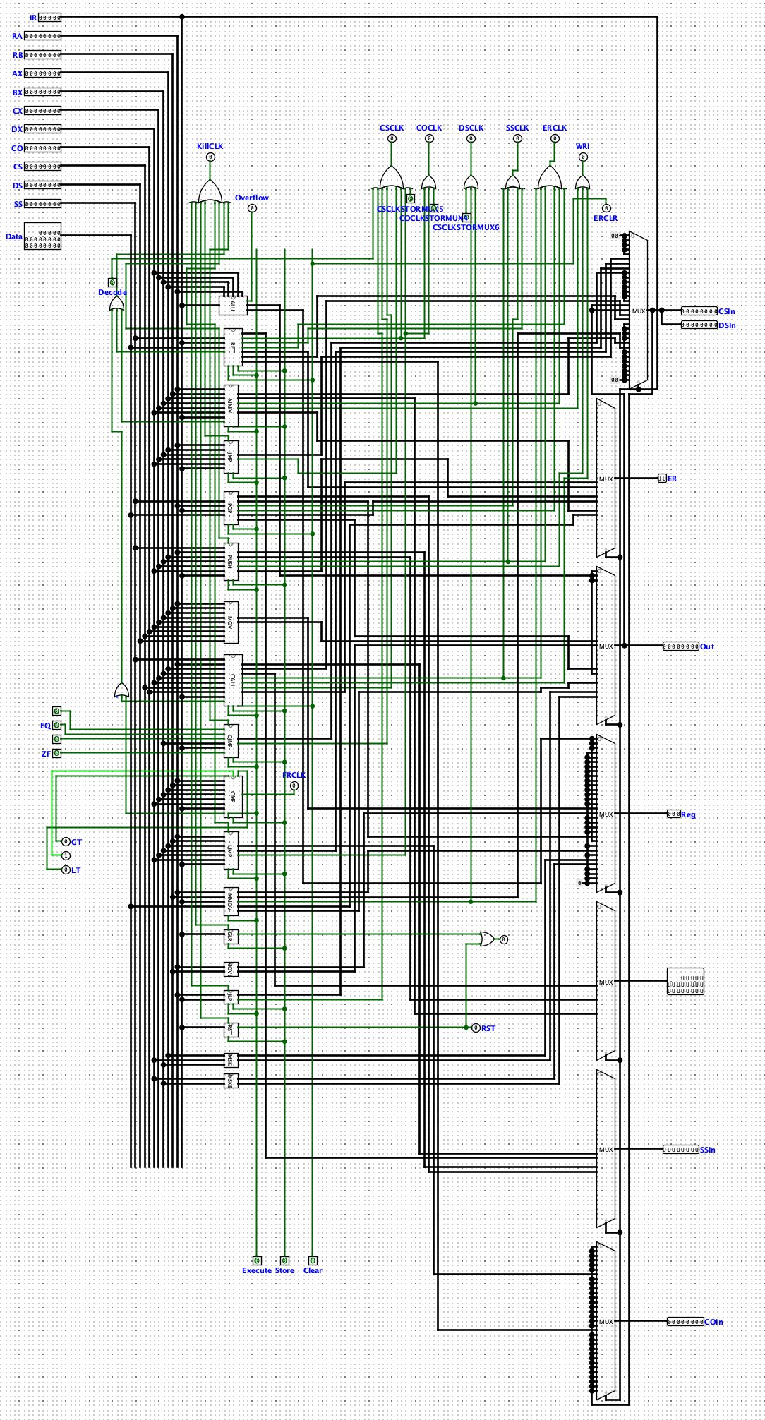
In the Control Unit, we can see that there are a lot of blocks on the left side carrying the instructions name, we can guess that it is in those blocks that the instructions are executed. Those blocks are (almost) all directly plugged to IR and when going inside the blocks we can see that they are also plugged to either RA, RA and RB, or none. We can assume that IR is gonna be the Instruction Register, RA and RB are gonna contain respectively the first and second operand of the instructions. Except for some special cases (mov, movl, msk and mskb), every instruction contains a AND logic gate plugged on each of the five last bits of IR where some of the bits are being NOT.
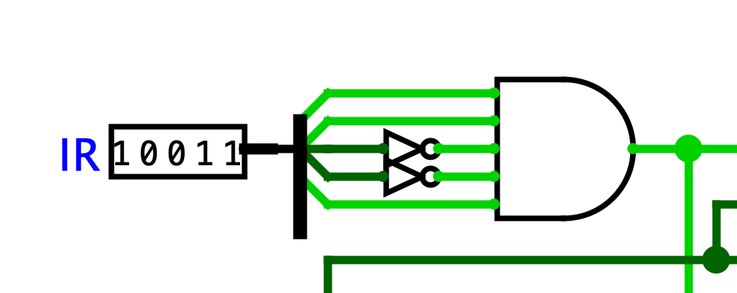 Fig 3. CMP instruction logic gate
Here we can see that cmp is switched on by the 10011 sequence (0x13), we can see that all these gates are unique so we can use them to retrieve the opcodes of all the instructions which gives us the following translation table :
| Opcode | Instruction |
|---|---|
| 0x0 | add |
| 0x1 | sub |
| 0x2 | mul |
| 0x3 | clr |
| 0x4 | rst |
| 0x5 | jmp |
| 0x6 | ljmp |
| 0x7 | jlp |
| 0x8 | jg |
| 0x9 | jge |
| 0xa | jl |
| 0xb | jle |
| 0xc | je |
| 0xd | jz |
| 0xe | jnz |
| 0xf | div |
| 0x10 | movl* |
| 0x11 | call |
| 0x12 | ret |
| 0x13 | cmp |
| 0x14 | push |
| 0x15 | pop |
| 0x17 | mmiv |
| 0x18 | mmov |
*The movl instruction isn’t directly plugged to IR, it is the multiplexers on the right that are plugged to IR and will execute (or not) movl depending on its value. But we can still guess its value by looking at the opcodes of example.data.
Now that we did that, we can try to guess how the operands are encoded. We will first look at the first two instructions of example.asm :
movl ax, 10
movl bx, 1
Those are encoded as : 10000a 100101
We know that 0x10 represents movl, we can assume that literals are transmitted as so in the machine code (0xa = 10). Seeing that ax is encoded as 0x00 and bx as 0x01, we can establish this register encoding table:
| Register | Encoding |
|---|---|
| ax | 0x00 |
| bx | 0x01 |
| cx | 0x02 |
| dx | 0x03 |
Last thing we need is knowing how labels are encoded. We will now look at the instruction that uses a label :
movl bx, :sub1
This instruction has been encoded as 100101. Now, we know that sub1’s value is 01. Since sub1 starts at the second instruction, which has index 1 in the RAM, we can guess that labels are encoded as their index in the RAM.
We now have almost everything we need to write our compiler. We can see two unknown instructions in the code of the program that we don’t have opcodes for, msk and mskb. We can see by looking at their module that they are setting the output register to :
msk : (ax & dx) | bx
mskb : dx | bx
As movl, those instructions are always “executed” since they are not directly plugged to IR but the multiplexer that is sending the result into output is so by manually setting registers and IR, we can identify the opcodes by looking at the value of the CU’s output register (we didn’t manage to find a way to examine the internal circuits of the multiplexers and reading the XML seemed painful). By trying the few opcodes left, we got :
| Opcode | Instruction |
|---|---|
| 0x1a | msk |
| 0x1b | mskb |
Exploitation⌗
Now that understand how the processor is working we can try to make a compiler to compile program.asm into program.data.
To do so we have to clarify a few things first :
- Another odd thing in the code is the
sub5value that is not preceded by colons unlike the others, we assumed that it didn’t matter and it worked (we added the colons in the file to make the compiler simpler). - Last thing we didn’t mention is that every instruction that needs less than two operands is padded with zeros so it stays 3-bytes long (we’d like to thank the challenge maker for putting zeros in the code when the second operand was useless, it makes the compiler way easier to make).
Here comes our compiler :
def get_instruction_type(instruction):
    if instruction[0] == ':':
        return 'label'
    return 'instruction'

def get_opcode(instr):
    translate_table = [
        "add",
        "sub",
        "mul",
        "clr",
        "rst",
        "jmp",
        "ljmp",
        "jlp",
        "jg",
        "jge",
        "jl",
        "jle",
        "je",
        "jz",
        "jnz",
        "mov",
        "movl",
        "call",
        "ret",
        "cmp",
        "push",
        "pop",
        "div",
        "mmiv",
        "mmov",
        "",
        "msk",
        "mskb"
    ]
    return format(translate_table.index(instr), '02x')


def get_label_encoded(word, labels):
    # Very ugly but there is only one so it's fine
    if '+1' in word:
        return '2f'
    else:
        return labels[word]

def get_operand_code(word, labels):
    regs = ['ax', 'bx', 'cx', 'dx']
    if ':' in word:
        return get_label_encoded(word, labels)
    if 'x' in word:
        if word in regs:
            return format(regs.index(word), '02x')
        else:
            return format(int(word, 16), '02x')
    else:
        return format(int(word), '02x')


def get_instruction_sequence(instruction, labels):
    words = instruction.split()
    opcode = get_opcode(words[0])
    op1 = '00'
    op2 = '00'
    if len(words) == 3:
        op1 = get_operand_code(words[1].strip(','), labels)
        op2 = get_operand_code(words[2], labels)
    return opcode + op1 + op2

if __name__ == '__main__':
    # don't forget to add the ':' in front of sub5 line 53 or compiler will crash
    program_file = './program.asm'
    output_file = './program.data'
    filestream = open(program_file)
    program = filestream.read().splitlines()
    filestream.close()
    labels = {}
    data = []
    for index, instruction in enumerate(program):
        type = get_instruction_type(instruction)
        if type == 'label':
            labels[instruction] = format(index - len(labels), '02x')
    # print(labels)
    for instruction in program:
        type = get_instruction_type(instruction)
        if type == 'instruction':
            data.append(get_instruction_sequence(instruction.strip(), labels))
    filestream = open(output_file, 'w')
    filestream.write(' '.join(data))
    filestream.close()
    print('Program has been compiled in :', output_file)
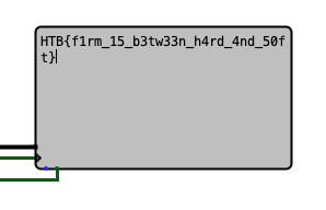
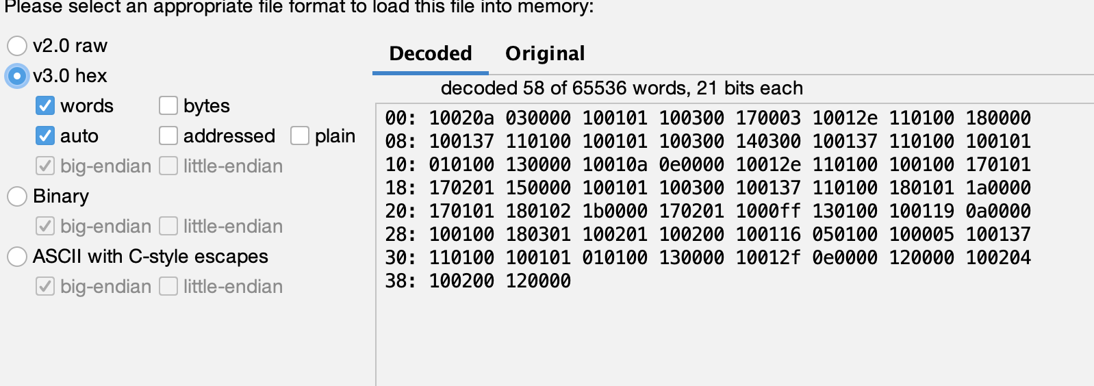 After a little while (a long while if you don’t increase the auto-tick frequency), the flag will be displayed on the TTY to the right.
